Sunday, April 27, 2014

OSPF Transit Capability

OK, a new feature introduced in OSPFv2 and back to RFC 2328 section 16.3 is the following:

16.3.  Examining transit areas' summary-LSAs

This step is only performed by area border routers attached to one or more non-backbone areas that are capable of carrying
transit traffic (i.e., "transit areas", or those areas whose
TransitCapability parameter has been set to TRUE in Step 2 of
the Dijkstra algorithm (see Section 16.1).

The purpose of the calculation below is to examine the transit
areas to see whether they provide any better (shorter) paths
than the paths previously calculated in Sections 16.1 and 16.2.
Any paths found that are better than or equal to previously
discovered paths are installed in the routing table.

The calculation also determines the actual next hop(s) for those
destinations whose next hop was calculated as a virtual link in
Sections 16.1 and 16.2.  After completion of the calculation
below, any paths calculated in Sections 16.1 and 16.2 that still
have unresolved virtual next hops should be discarded.

so what does it mean in Plain English?!!
Friday, April 25, 2014

OSPF Neighbors at Different Subnets!!

Yesterday we had many challenges at facebook Group about different Cisco IGPs Cases , and one them was about configuring OSPF neighbors but in different subnets, so the only Case i Knew According to RFC2328 was Point-to-Point connection using ip unnumbered and virtual links, that's always works fine .

But what about multi-access interfaces e.g: fastethernet ?!! That was a bit confusing at the beginning but i had to go for a workaround solution which PPPOE + ip unnumbered which worked like a magic :D

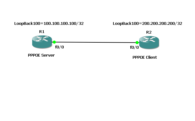
So As usual we will use our simple Topology with two routers with R1 as PPPOE server and R2 as PPPOE Client:
R1 ==> fa0/0 ==> IP address should be 10.10.10.1/24
R2 ==> fa0/0 ==> IP address should be 20.20.20.20/24


So I will move These IPs to Loopback 0 in Both Routers and We will Start from There.

R1 (PPPOE Server):

Tuesday, April 15, 2014

EIGRP "Named Mode" First Thoughts!!

When I started to read about this new operational mode for Cisco which is called EIGRP Mode, I keep telling my self what is the point here Cisco, i don't see any benefits but typing more commands!, but bear with me :)

According to Cisco this mode is available on 15.0(1)M - 12.2(33)SRE - 12.2(33)XNE - Cisco IOS XE Release 2.5 which is pretty new one.

Cisco now called our old EIGRP configuration "Classic Mode" which we used to type AS number, now by this new configuration we won't type AS Number but instead we are going to type "Virtual-Instance Name"!,
Cisco aims by this new config to get what is called "Unified Configuration Solution" to provide ONE place to configure all of EIGRP and to provide ONE common way to define a feature , so let's take a look at our usual Basic topology and I am going to configure R1 with the old Classic Mode and R2 with the new Config Named Mode just to show how differences are but with the same overall final result.


Friday, April 11, 2014

EIGRP AS go figure!

I know it has been a lot of time since i blogged but here I'm again :)

Have you ever faced a situation that you want to peer with a router using EIGRP and you can't even touch or telnet to that device, well you 're gonna tell me so where is the catch here ?!! go with your normal config and in your lovely config mode and type (config)#router eigrp AS-Number and you should be good to go!

and here is the catch you didn't get it, I don't know The EIGRP AS dude!!!!!!!
so again to keep our case pretty simple i will just use two router with their loopbacks, so nothing fancy here:


Wednesday, December 22, 2010

Cisco Design journey / Brief Notes

i started lately to go through some cisco design topics, although i found it extremely boring for conf t guy like me but i will be so helpful .

The Cisco Enterprise Architecture comprises the following six major functional areas (also called modules):

■ Enterprise Campus
■ Enterprise Edge
■ Service Provider
■ Enterprise Branch
■ Enterprise Data Center
■ Enterprise Teleworker

Tuesday, December 14, 2010

IPv6 Notes -Part2

IPv6 Address Autoconfiguration:

■ Stateful autoconfiguration : using DHCP .
■ Stateless autoconfiguration : using EUI-64 process .
  - EUI-64 :
standard places the hex value FFFE into the center of the MAC address for this purpose. Finally, EUI-64 sets the universal/local bit, which is the 7th bit in the Interface ID field of the address, to indicate global scope.
Here is an example. Given the IPv6 prefix 2001:128:1F:633 and a MAC address of
00:07:85:80:71:B8, the resulting EUI-64 address is
2001:128:1F:633:207:85FF:FE80:71B8/64

ND Messages Types:

Router Advertisement (RA) : Routers advertise their presence and link prefixes, MTU, and hop limits.
Router Solicitation (RS) : Hosts query for the presence of routers on the link.
Neighbor Solicitation (NS) : Hosts query for other nodes’ link-layer addresses. Used for duplicate address detection and to verify neighbor reachability.
Neighbor Advertisement (NA) : Sent in response to NS messages and periodically to provide information to neighbors.

Monday, December 13, 2010

IPv6 Notes -Part1

- In IPv6, as in IPv4, unicast addresses have a two-level network:host hierarchy (known in IPv6 as the prefix and interface ID).


 ipv6 address types:

    Unicast :
  • Aggregatable Global Addresses: 
begin with binary 001. This value can be written in prefix notation as 2000::/3, which means “all IPv6 addresses whose first 3 bits are equal to the first 3 bits of hex 2000.

  • Link-Local Addresses:
begin with FE80::/10. The Interface ID portion of the address is derived using the modified EUI-64 format .

     Multicast :

IPv6 always begin with FF as the first octet in the address, or FF00::/8. The
second octet specifies the lifetime and scope of the multicast group. Lifetime can be permanent or
temporary. Scope can be local to any of the following:
■ Node
■ Link
■ Site
■ Organization
■ Global